Cone Crusher
Cone Crusher for sale
Although the jaw crusher and gyratory crusher may be adapted to the duty of secondary and tertiary crushing, the greater capacity of the cone crusher results in its almost universal application to crushing of strong, abrasive rocks.
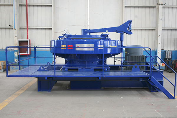
Cone crushers are a development of the gyratory crusher patented by Symons in 1930. The crusher comprises a 'gyrating' upright conical crushing member, the head lined with mantle, within a conical crushing chamber lined with wearing metal usually described as 'concaves'. The crushers are usually designated by the diameter, in feet or millimetres, of the head. The significant difference from the gyratory crusher is that the crushing chamber is now also in the form of an upright, truncated cone and the 'gyrating' cone, having an angle of about 45 ~ is supported entirely from beneath by the eccentric bush assembly. A further significant difference is that the eccentric shaft in modern machines rotates very much more rapidly (>200rpm) than that the gyratory crusher. As a result, the crushing action may be considered to fall between compression and impact, resulting in improved energy utilization and product shape. One particular criticism of the cone crusher has been the tendency to produce particles of a flaky shape owing to the geometry of the crushing chamber. This can be counteracted by the use of low reduction ratios and ensuring that the crushing chamber is always full of material, a condition known as 'choke feed'. The cone crusher is available in several forms to most suit the requirements of the secondary and tertiary stages of comminufion. The secondary cone (standard cone) crusher has a steeply inclined, sometimes stepped, crushing chamber formed by the concave and a flatter less steeply inclined conical crushing member. The reduction ratio achieved varies from 4:1 to 8:1. The tertiary, short-head-cone, crusher has both crushing chamber and cone steeply inclined to promote the gravitational flow of more finely sized material. The reduction ratio varies from 4:1 to 6:1. A great deal of experience and expert knowledge is now available to optimize the detailed design of the crushing chamber, eccentric throw, etc., in terms of feed size distribution, desired product, power consumption and liner life.
Cone Crusher work process
The maximum particle size of the product is largely controlled by the distance between the mantle and concave at the open side of the crusher. Since this clearance cannot be easily measured the closed side setting is usually determined by crushing a piece of malleable lead. As a 'rule-of thumb', the maximum product size is approximately twice the closed side setting. This may be varied within limits by either raising the cone or lowering the concave assembly. Both methods are employed as in (a) the use of hydraulic support of the eccentric shaft and (b) machine threads or hydraulic support of the crushing chamber assembly. Both provide a method for compensating for wear of the liners and providing overload release in the event that uncrushable material, e.g. tramp metal is contained in the feed. Moreover, hydraulic support provides a means of automatic control upon product size and/or maximum power input without fear of overloading the crusher. This can result in significant improvements in plant productivity. It is common practice to operate secondary and tertiary crushers and grinding mills in closed circuit with a sizing device such as a screen or a classifier as appropriate. The product from the comminution device passes to the sizing unit where oversize particles are removed and then recirculated to the comminution device. With such a circuit it is possible to control the top size strictly, to prevent excessive generation of undesirable fines and to save upon power consumption.


